Last Updated on July 22, 2024
Sargent IC Core Pinning Calculator for 3 Level Master Key Systems
When we received a call from a major sports team to rekey their entire facility we were excited. Then we learned they had Large Format IC Cores (LFIC) and our excitement quickly faded. This customer wanted a three-level master key system: a grand master key that worked everything, a sub-master keys for each division, and change keys (individual keys that work only one door).
If you’ve ever tried to calculate a Sargent IC Core pinning chart with three levels, you know that it is a very time consuming and laborious task.
Sargent has published a LFIC pinning worksheet that walks you through the calculations, but the issue is, its mathematically intensive and takes about 5 minutes to completely fill out for EVERY door in your system.
Why waste your time when we’ve done the work?
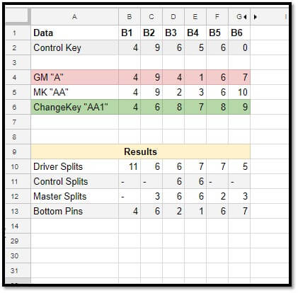 ACME Locksmith has created a Sargent IC Core Pinning Calculator, in an excel spreadsheet, that removes every manual calculation. As with the form provided by Sargent, you will need a master key system generator that gives you a selection of key cuts to use in your master system. You must have MS Excel to use this spreadsheet.
Then, just input those cuts into our spreadsheet and we will calculate the driver pins (top pins), control pins, master pins and bottom pins that you need to pin up the cylinder.
This will save you hours of work for the cost of two foo-foo coffees at one of those major coffee chains.
Just $14.99. By Now, Payment Will be Processed Through PayPal for your protections but you do NOT need to have or setup a paypal account.
Not convinced it’s worth it? If you’d rather go through the process, here’s the manual way to calculate the pins.
Basic Process of Loading the Core
The 6300 LFIC uses a control key whose cuts match the GM key of the system n positions 1,2,5 and 6.
The chamber stack value for the Sargent IC core is normally calculated by using a stack value of 15 in positions 1, 2, 5, and 6. This is the total value of the bottom pins, master splits and driver pins that would be required to pin the core (based on the keying levels).
In chambers 3 and 4 of the 6300 LFIC (removable core), the stack value is 20. This is done to allow the control key to achieve a shear line in chambers 3 and 4 of the control sleeve.
Important
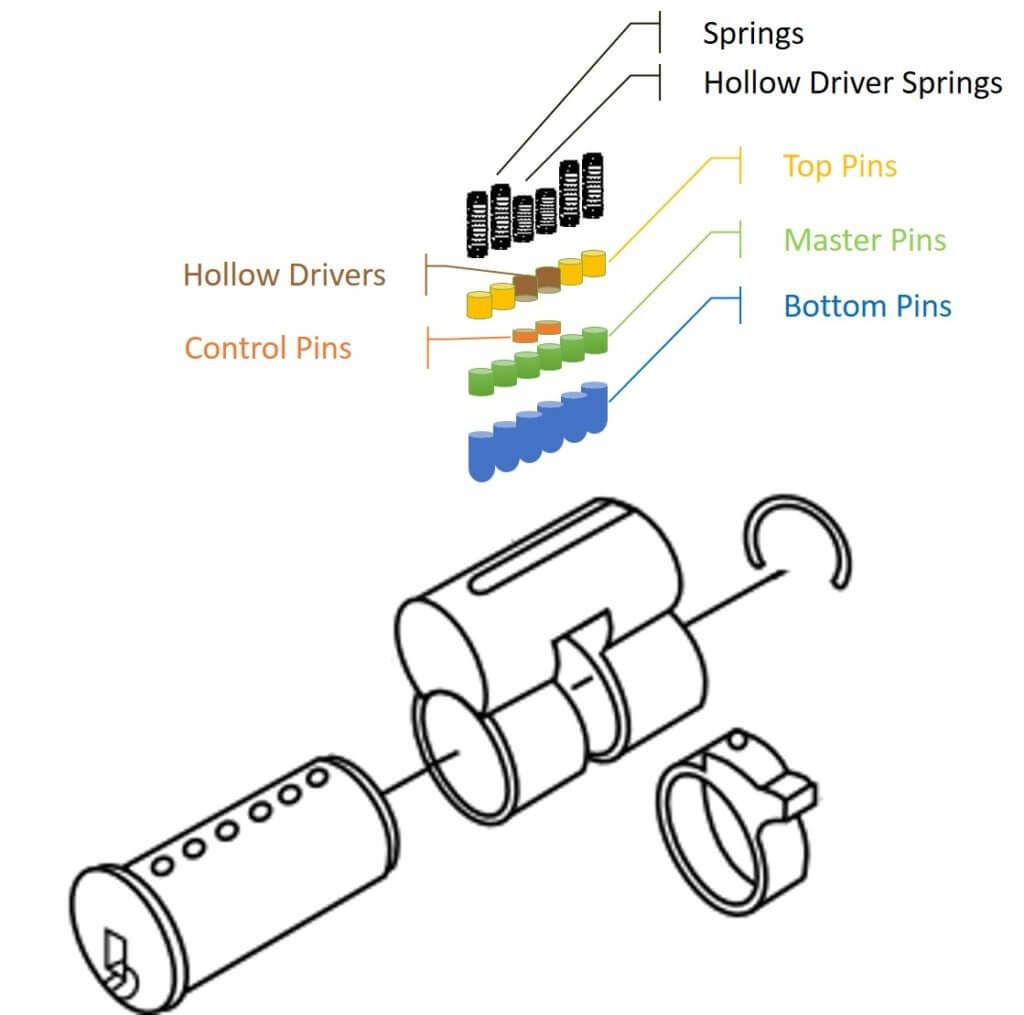
Cylinders master keyed at the factory prior to January 2009 use hollow drivers and SARGENT recommends their continued use. Hollow drivers must be used in chambers 3 and 4. A different spring is used in conjunction with the hollow drivers. These special drivers and springs are included in a special pinning kit available from Sargent (#437 RC/UL) or available individually.
Cylinders factory master keyed after 12/31/08 use standard drivers in all positions and use a single spring (Sargent p/n 13-1769) in all positions.
Once you’ve determined the pins remove the spring clip and disassemble the barrel from the cylinder body and sleeve (or load from the top if you have the Sargent top-loading
kit (p/n 436-1).
With sleeve positioned correctly in cylinder body (as shown above), load barrel and cylinder body.
Finish assembling by applying retaining ring to the barrel.
Calculating the Sargent IC Core Pinning for One Cylinder
-
- Obtain a list of operating keys. Use your favorite locksmith software to generate a master key chart.
- Choose the bittings from the master key chart you are going to use for the GM, Master and Change Keys for each door.
- Print out a worksheet for each door in your system Sargent IC Core Pinning Worksheet. So if you have twenty doors, you need twenty worksheets.
- Reference one of those sheets while performing the below
- Enter the control key bitting on line 3.3. Even though the work sheet doesn’t start here, I like to start here because your GM key will need to match the bitting in positions 1,2,5 & 6. Side note: our spreadsheet takes this into account for you. Once you enter the control key, your GM key cuts in these positions become fixed to those of the control key.
- Enter the Grand Master, Sub Master, and change key bitting in section 1. Careful, the work sheet refers to the individual door key as as control key, not to be confused with the control key used to remove the cores that you entered on line 3.3. You want to enter the change key here.
- In section 2, the bottom pins are the smallest number from each chamber of the keys found in section 1. Enter the smallest values here.
- In section 2, the master pins are the difference in the smallest and largest pins from section 1 in each chamber.
For example: If bit 1 in the Grand Master, Sub Master, and Control Keys were 1,2,5 (respectively) the difference between the smallest and largest value is 5 – 1 = 4. The value “4” would be entered here for bit 1.
- Calculate the control splits
- Record the bitting of bit 3 and 4 and add 8 to these numbers.
- Subtract the largest numbers of bitting in bit 3 and 4 found in sections 1 from the added values in previous step.
- These numbers are the control splits for bit 3 and 4.
- Calculate the Top (Driver) pins
- On line 4.1 add the sum of the value of the bottom pins, master splits, and the control splits.
- On line 4.2 subtract the amount in line 4.1 from the prefilled out values on line 4.
- Transfer the values of the driver, control, and master pins to section 5 for quick reference.
- If everything was done correctly you will have a total of 15 in each of bit 1,2,5, and 6 and 20 in bits 3 and 4.
- Repeat for next door.
OR THEY EASY WAY,
- Purchase our easy-to-use excel spreadsheet that has all of the calculations done for you
- Enter the customer name and door label
- Enter your key cuts for that door that you recorded from your master pinning chart
- Print the sheet for your records for the bitting of that door.
- Repeat for the next door.
Just $14.99. Buy Now, Payment Will be Processed Through PayPal for your protections but you do NOT need to have or setup a paypal account.